Abstract
As a mean to enhance the capabilities of the roombot to undergo reconfiguration, local proximity sensors, hall sensors and infrared sensors, have been mounted on the roombot’s face. With these sensors a study of the different kind of misalignment between two roombot’s faces were done in this report. It demonstrates that due to the numerous symmetrical solutions, the sensors alone cannot be used to differentiate them.
Some experiments was done to characterise and choose the optimal hall sensor magnet pair and to characterise the infrared sensor. For further experimentation, the AO hall with a 4mm magnet ant the RA hall with a 3mm magnet was chosen. This two sensor magnet pairs have a range of around 1mm up to 4mm in head on direction (z) and around 1.25 up to 3mm in lateral direction (R). The infrared sensor operates from 0.8mm to 10mm in z and detect a ∅ (rotation around y) misalignment in a range of 2.7° to 9°. The infrared sensor mounted horizontally cannot detect a misalignment in tetha (rotation around x).
After having done further testing on the roombot, the hall sensors enable the detection of a misalignment and therefore indicates if it is safe or not to activate the Active Connection Mechanism (ACM) to dock.
Test Setup and Result
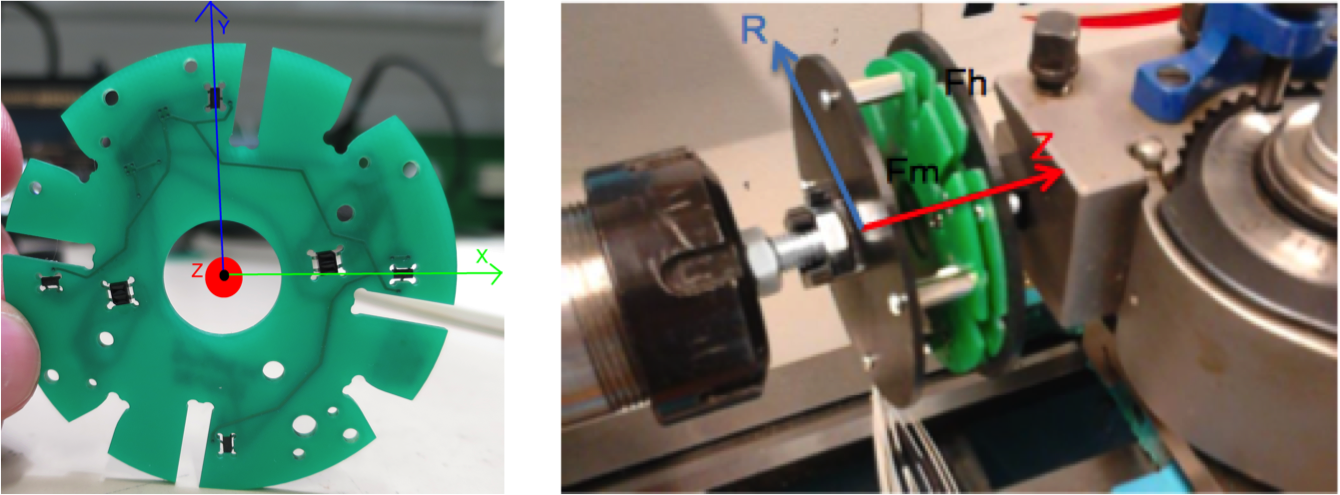
Figure 1: The mounted sensors on the roombot face (left), test setup where the roombots face is aligned and fixed on a lathe (right)
The 4 hall sensors are positioned on the outer circle and the two infrared sensors are placed closer to the center. Fm: face containing the magnet and Fh: face containing the hall sensors. The face Fh is moved relative to the face Fm in head on (Z) and radial dirrection (R). Datas have been collected in both direction for 4 different type of hall sensors, having different sensitivity and 4 different magnet size (2mm, 3mm and 4mm magnet) in all possible configuration. Then, a caracteristic surface curve for each hall-magnet pair has been fitted on the datas (see figure 2).
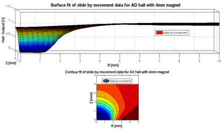
Figure 2: Result obtained for one hall-magnet pair
The dark blue region is the saturation zone, the orange red region are considered as the undetectable region of the hall sensor combined with a 4mm magnet size. Between these region is detectable zone of the hall-magnet pair. The choosing criterias of a hall-magnet pair are:
- A small saturation region
- A large detectable region
- A smooth transition in the detectable region
Conclusion
Futher testing on a real situation needs to be performed to better evaluate the efficiency of using hall and infrared sensors as local sensory feedback during